The first and perhaps most obvious requirement is the power supply to the module. The designer has two choices either to use the modules on board linear power regulator or to supply a suitably regulated 3.3V supply.
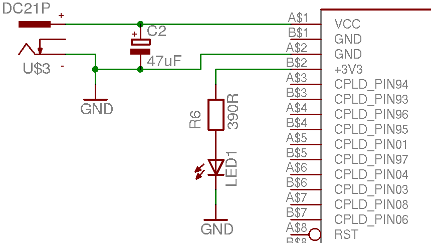
If the designer chooses to use the on board regulation a simple supply providing 5-12V DC is required, although there is adequate smoothing on board an additional 47uF electrolytic type capacitor will ensure any transient power sags will be dealt with. If using this supply method the modules 3.3V rails can supply 50mA or so of additional current to external devices such as buffers or small logic devices. Good decoupling and grounding must be used if the module supplies external devices.
On board regulation is not efficient the exact power usage is outlined in Figure 2.9, “Graph of EB675001DIP power usage”
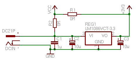
If the on board regulation will not meet the designers power requirement a 3.3V off board regulator can be used to supply power to both the module and the other application hardware. Because the user CPLD can alter the required power, provision for a maximum current of 0.5A (1.6W) should be made for the module. The circuit outlined in Figure 4.5, “Schematic fragment of flexible EB675001DIP power supply” provides for both on board or off board regulation. Only one of the zero ohm resistors R1 and R2 should be fitted. R1 for off board regulation and R2 (with REG1 omitted) if on board regulation is to be used. R1 should be used in off board mode to ensure the internal regulator is not placed in parallel with the external one.
The linear regulator methods (both on board and external) work well for low input voltages and can produce adequate power for small circuits without requiring extensive heatsinks and cooling. For higher power or input voltage requirements a DC to DC converter can be used to generate 3.3V with much greater efficiencies.
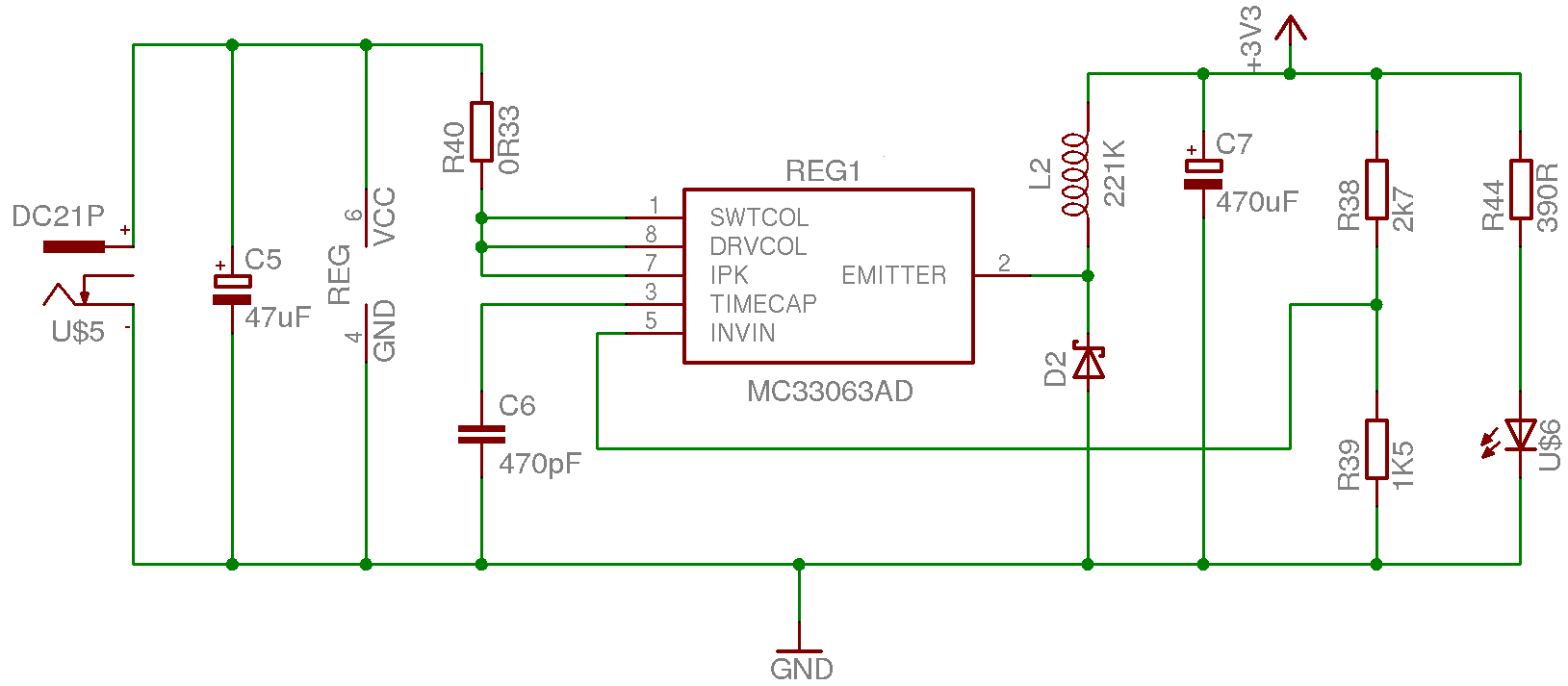
One possible circuit is outlined here, this is a simple step down switcher arrangement capable of producing 3W from a wide input voltage. The example circuit shown here can be built from simple through hole components and is generally insensitive to layout issues providing the leads are kept short.
The Texas Instruments MC33063 is a simple eight pin device which can be configured for several modes of operation in addition to the step down configuration shown here. The inductor L2 is a 220uH coil a suitable part might be a TOKO 822LY-221K (this part would limit the output current).
It is of course possible to create this circuit using surface mount components, MC33063AD and A814AY-221K would be the major parts, although circuits and devices with superior performance may be selected in SMT designs.
There exist a large number of component and circuit choices for DC to DC converters and the user should select the appropriate one for their needs.