The EB675001DIP has four expansion connectors a designer might be interested in (the pinouts are detailed in Section 2.10, “Expansion connectors”).
The two main sixty way expansion headers (PL3 and PL4) are on a standard 0.1inch (2.54mm) grid the Appendix B, Mechanical drawing has details of the exact dimensions for all connectors. These connectors carry the signals from the CPU and User CPLD these signals are fully buffered and are 5V tolerant. The buffered RS232 serial signals are replicated on PL4 pins A26 to B29 if the 9way D connector isn't used. The SERIAL_EN signal on B30 allows the serial buffer to be disabled which allows the unbuffered serial signals to be used on B16 to B25.
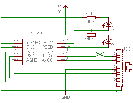
The Ethernet header (PL7) is again a standard 0.1inch 2x5 header which is only available if the module is purchased without the Ethernet jack fitted. A suitable RJ45 jack with integral magnetics and LEDs is the Bothhand L5041 which may be obtained along with the module if desired. The Ethernet expansion connector allows the connector to be placed in a more convenient position within a larger design.
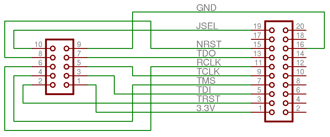
The JTAG header PL6 gives access to the on board JTAG chain comprising the OKI CPU, system CPLD and the user CPLD. The layout is a 2x5 0.1inch (2.54mm) pitch header which can be connected to a standard multi-ICE 2x10 connector with a simple IDC cable.
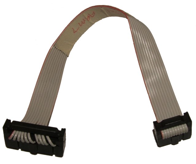
This schematic of the cable while accurate does not make the simplicity of the cable immediately obvious. An image of a completed IDC cable gives a better representation.