The PlayXSVF utility requires a boundary scan JTAG file in the Xilinx® XSVF file format. The XSVF file format is a binary representation of the standard Serial Vector Format (SVF). The formats and their differences are described fully in the Xilinx XSVF Appnote.
Generating the XSVF file is easily performed using the Xilinx® WebPACK® tools. The worked example presented here should provide the reader with enough guidance to produce the results they require.
A project is opened in the WebPACK® project navigator (in this case the user CPLD VHDL template file provided on the EB675001DIP resources web page). The "Implement Design" selector allows the "Optional Implementation Tools" list to be expanded. The "Generate SVF/XSVF/STAPL File" action should then be selected and run (typically by double clicking).
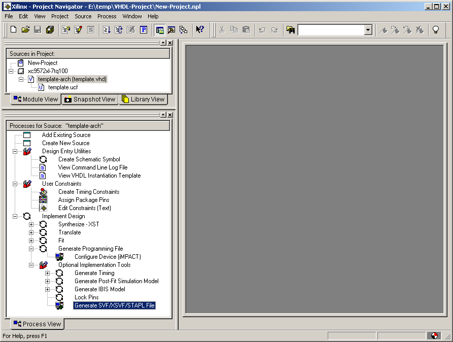
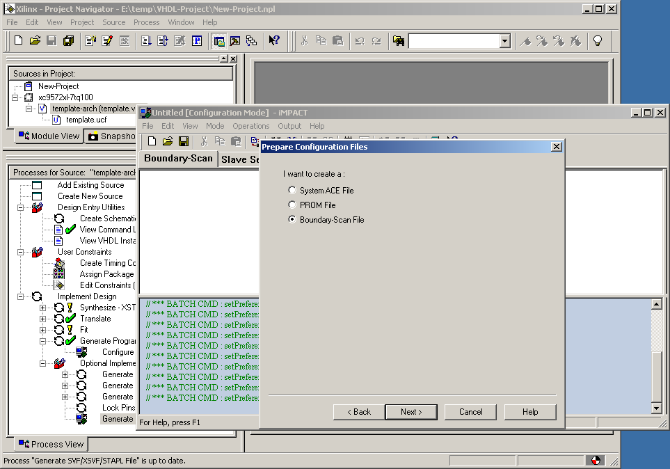
If not already built the WebPACK® tools will run and synthesise, translate, fit and generate a programming file, this can be seen from icons appearing next to each stage in the "Implement Design" section of the navigator. The Impact utility will then be started and a prompt for the type of file to create will be shown. The "Boundary-Scan File" option should be selected and the "next" button clicked.
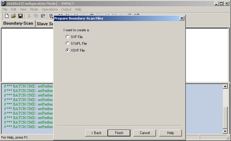
Impact will prompt for the type of Boundary scan file. Select the "XSVF File" option and the "Finish" button.
Impact will prompt for the name of the XSVF file to save. Provide a suitable file name and click on the save button.
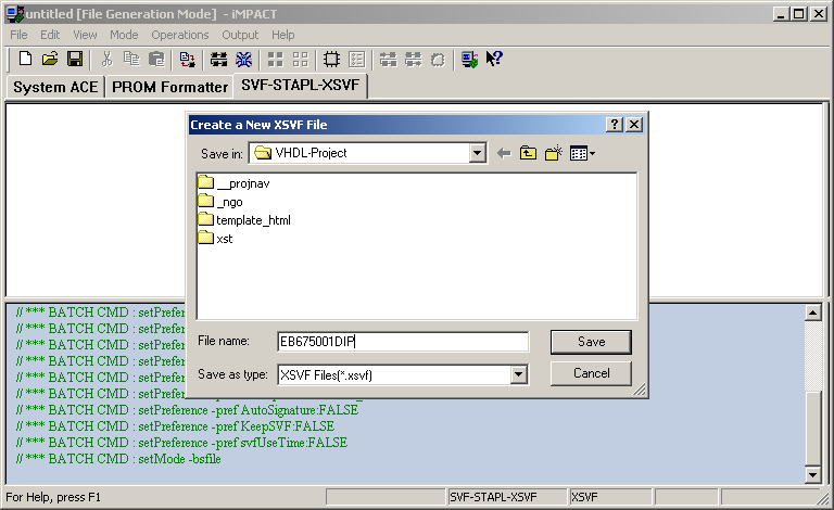
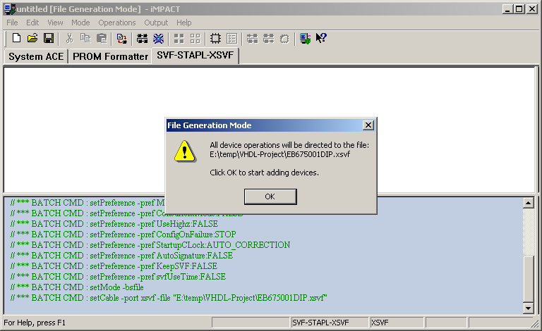
Impact will confirm the location of the XSVF file. The dialog should be closed by clicking the "OK" button.
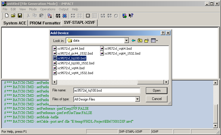
Impact will next prompt for the location of a design file of the CPLD to be programmed. This is typically located within the Xilinx® install directory for example c:\Xilinx\xc9500xl\data\xc9572xl_tq100.bsd. The appropriate file should be selected and the "Open" button pressed.
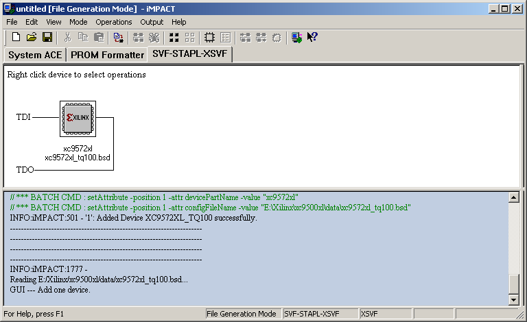
Impact will now display an diagram showing a JTAG chain with a single xc9572xl.
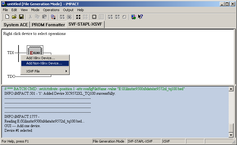
The JTAG chain needs to be extended to include the ML675001 processor. The flashing cursor should be placed to the left of the xc9572xl icon with a button click. The right mouse button should be pressed to open a menu and the "Add Non-Xilinx Device..." entry selected.
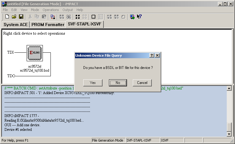
Impact will prompt for a BSDL design file for the OKI ML675001. A design file in not required to successfully generate user CPLD XSVF programming files, select the "No" option.
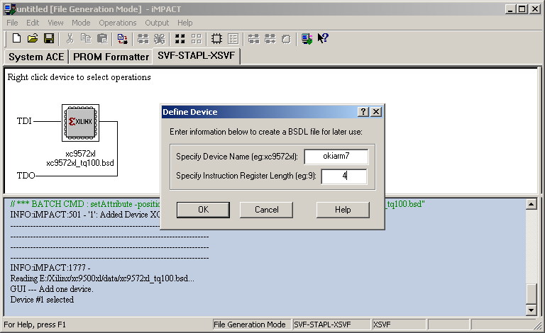
Impact will prompt to enter the information to define the ML675001. Enter a suitable name for the device such as "okiarm7" and enter 4 for the Register Length and select "OK"
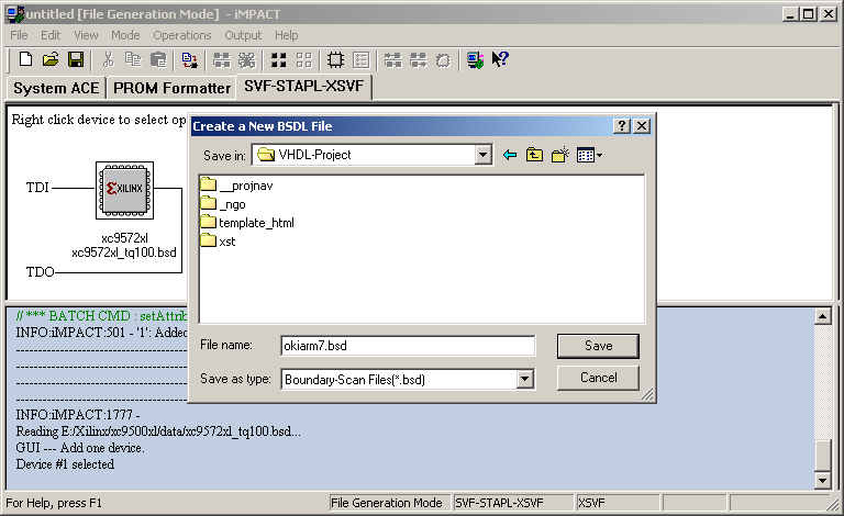
Impact will prompt for a location to save the generated BSDL file, select a suitable location (typically within your project directory) and select "Save"
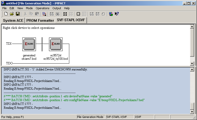
Impact will now display an diagram showing a JTAG chain with the OKI ML675001 followed by the Xilinx® xc9572xl.
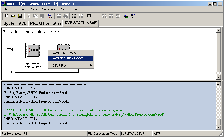
The JTAG chain needs to be further extended to include the system CPLD. The flashing cursor should be placed between the OKI ML675001 icon and the xc9572xl icon with a button click. The right mouse button should be pressed to open a menu and the "Add Non-Xilinx Device..." entry selected.
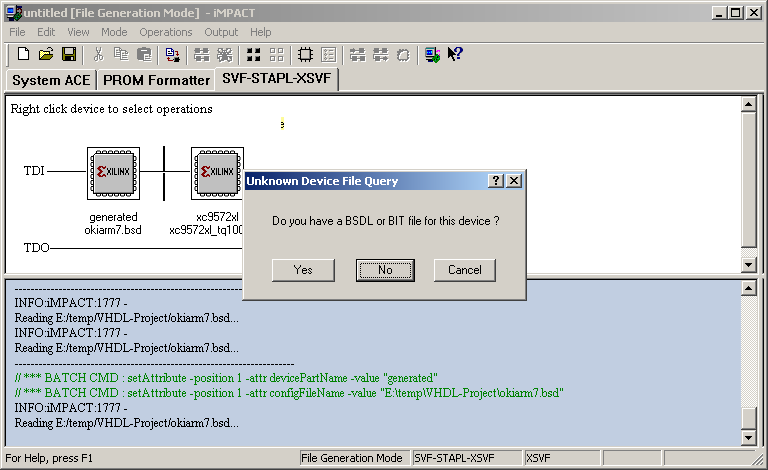
Impact will prompt for a BSDL design file for the system CPLD. A design file in not required to successfully generate user CPLD XSVF programming files, select the "No" option.
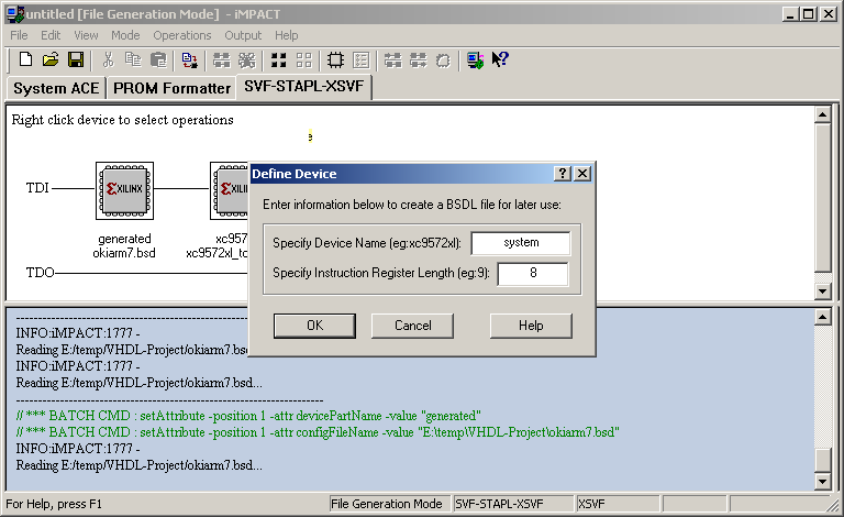
Impact will prompt to enter the information to define the system CPLD. Enter a suitable name for the device such as "system" and enter 8 for the Register Length and select "OK"
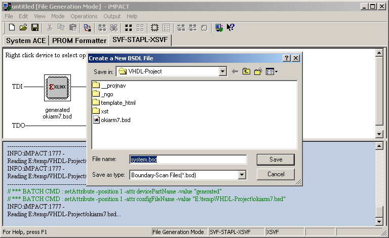
Impact will prompt for a location to save the generated BSDL file, select a suitable location and filename (typically within your project directory) and select "Save"
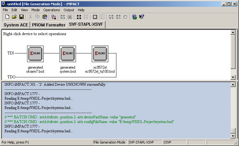
Impact will now display an diagram showing a JTAG chain with the OKI ML675001 followed by the system CPLD and finally the Xilinx® xc9572xl.
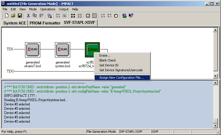
Once the JTAG chain has been constructed the next task is to assign a JEDEC configuration file to the user CPLD. The xc9572xl should be highlighted by clicking with the left mouse button. Once highlighted the right mouse button should be clicked which will open a menu, select "Assign New Configuration File..." from the menu.
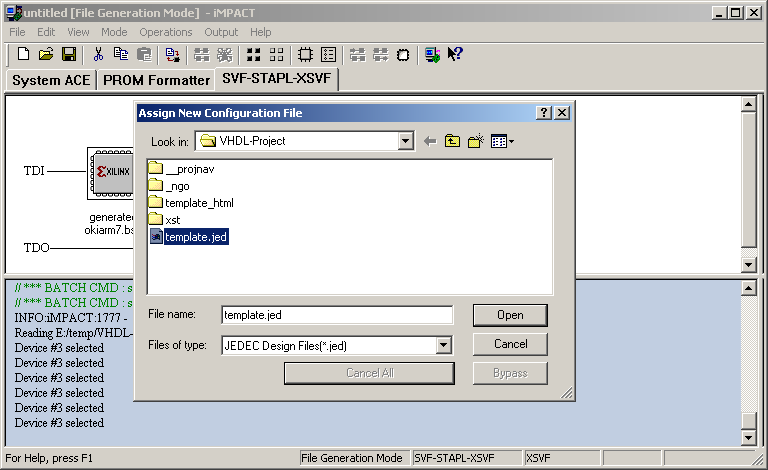
The "jed" file from your project should be selected and the open button selected.
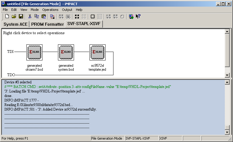
Impact will now display an diagram showing a JTAG chain with the OKI ML675001 followed by the system CPLD and finally the Xilinx xc9572xl with the selected JEDEC file name.
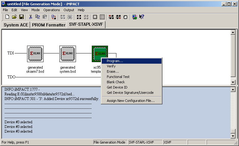
The final stage is to actually "program" the xc9572xl which will send all the programming actions to the XSVF file. The user CPLD should be selected with a left mouse click and the right mouse button used to open a menu, the "Program..." entry should be selected from the menu.
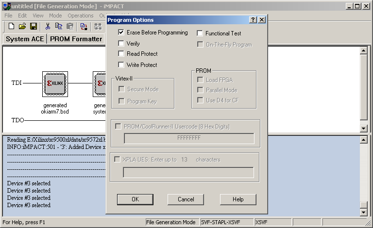
Impact will show the "Program Options" menu, typically all the options should remain unset apart from the "Erase Before Programming" selection. Once the required options have been selected the "OK" button should be selected.
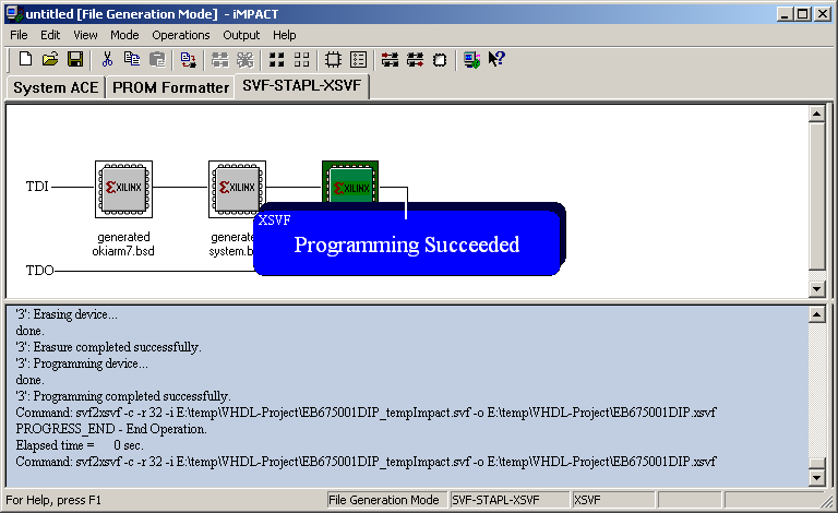
The programmer will run and Impact will display the blue "Programming Succeeded" box.
Impact may now be closed, Impact may prompt to save the JTAG chain, this can be useful if the task is to be repeated. The XSVF file is now available to use with the PlayXSVF utility.