EB675001DIP Bootstrap Guide |
|
Contents
©2004,2005 Simtec Electronics
Introduction
This document describes how to bootstrap an EB675001DIP module. This procedure is only required if ABLE or some other loader is not already programmed into the NOR flash of the module. The module is shipped with ABLE pre-programmed.
This procedure is usually only required when the NOR flash has become corrupted, either because of a failed update or because some user supplied code has failed, possibly cased by a bug in development code.
This procedure is a special-case usage of the "Downloader" Initial Program Loader (IPL), freely available from the EB675001DIP resources. For more detailed explanation of this tool and its operation, please refer to the Downloader User Guide.
Overview
This procedure involves the following steps:
- Setting the Boot DIP switches to boot from the OKI ROM Loader
- Identify which serial port the unit is connected to
- Sending 5k of zeros to initialise the OKI ROM Loader
- Sending "Downloader" IPL
- Using XModem to upload the RAM-load version of ABLE
- Using the ABLE command line to write a fresh copy of ABLE to flash
- Setting the Boot DIP switches back to boot from NOR flash
This document refers to version 2.09 of ABLE however later versions may be available, the procedure is not changed in any way except for a change in version numbers in some commands.
This procedure is slightly unusual because it uses an additional build of ABLE which can be RAM loaded, aside from its special ability to be loaded in this way it is a fully functional version of ABLE and can be used in the normal way once booted.
Resources
The required resources to perform this procedure are:
- PC with a free serial port
- Suitable serial terminal program
- Null modem serial cable
- EB675001DIP module
- File of 5K of zeros (not needed for Linux)
- Downloader utility pre-built hex record
- RAM-loadable copy of ABLE
- Romwrite copy of ABLE
- TFTP server to serve files e.g. the romwrite copy of ABLE to be programmed.
Performing this procedure with minicom under Linux/UNIX
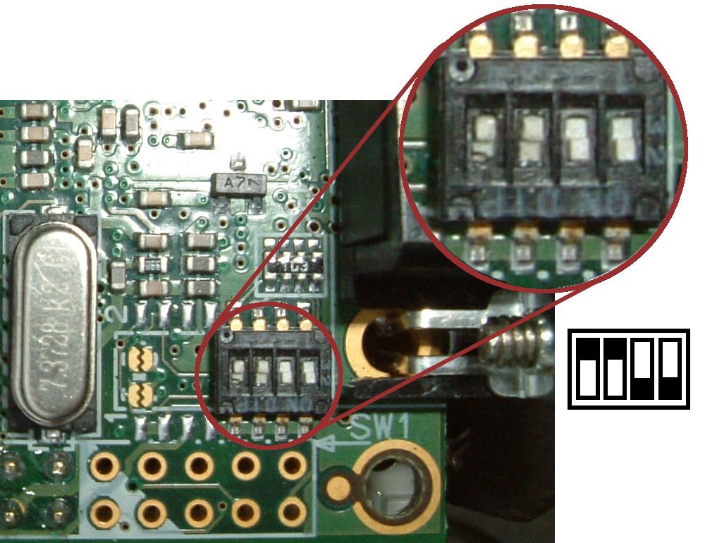
Setting the Boot DIP switches to boot from OKI ROM Loader
 This
step should be performed with the module power turned off. The
OKI ML675001 SOC has a 4k boot ROM. This ROM-based loader is
selected by setting DIP switches 3 and 4 (Boot 0 and Boot 1) to the off
position.
This
step should be performed with the module power turned off. The
OKI ML675001 SOC has a 4k boot ROM. This ROM-based loader is
selected by setting DIP switches 3 and 4 (Boot 0 and Boot 1) to the off
position.
Connect a null modem lead
Connect a null modem lead between a serial port on the PC and the EB675001DIP modules 9way D RS232 port.
Identify which serial port the unit is connected to
Identify which serial port the EB675001DIP is connected to and ensure a note is made of the correct device node. The serial device node on Linux or UNIX will be in the form of a special character device in the /dev directory, e.g. something like /dev/ttyS0 or /dev/ttyUSB0. The names of these special character devices are system dependant, on a Linux system the serial ports connected directly to the PC motherboard are usually /dev/ttyS0 and /dev/ttyS1 and a port connected to a USB dongle would be /dev/ttyUSB0
Start minicom and ensure the correct settings are selected (Default is Ctrl-A o). These settings are 115200 baud, 8 data bits, no parity and 1 stop bit. Obviously Minicom should be using the correct serial port as noted earlier.
Apply power to the module
Turn on the external DC supply.
Sending 5k of zeros to initialise OKI ROM Loader
This is readily achieved under Linux by using the dd command. Closing minicom is not required; simply switching to another console as the same user is sufficient.
Simply issue the command:
dd if=/dev/zero bs=5120 count=1 of=/dev/ttyS0
…replacing the output device with the correct one noted earlier.
The minicom screen should output the word "Ready" some additional "." characters are also normal.
Sending "Downloader" IPL
The "Downloader" IPL is also transferred using the dd command:
dd if=eb67xxxx-dl.hex of=/dev/ttyS0
…again replacing the output device with the correct one noted earlier.
Once the transfer is complete minicom should display:
User program download finished.

Select next operation.
    0 : Download other program.
    1 : Start user program.
> .
…answer by typing 1
The Downloader utility has been transfered into SRAM by the OKI ROM Loader. It initialises the DRAM of the EB675001DIP and starts an XModem transfer into the SRAM.
Using XModem to upload the RAM-load version of ABLE
Once the "Downloader" IPL is running, minicom should display:
User program start.
>Simtec EB675001DIP
        (c) 2004 Simtec Electronics
Simtec Electronics XModem code download tool
(c) 2004,2005 Simtec Electronics
RAM Size: 0x02000000 bytes
Download address: 0xC0000000
minicom should now be used to start an XModem transfer. By default this is available by using "Ctrl-A s", which should prompt with an upload dialog asking for transfer type; select XModem from the list. The RAM-loaded copy of ABLE should be selected from the filesystem (named eb675001dip-able-ram-v209.bin) by pressing Space and then Return. The XModem transfer will proceed, displaying number of sectors and kilobytes transfered.
Using the ABLE command line to write a fresh copy of ABLE to flash
Once executing, the ABLE command line may be used as normal. (see the ABLE Documentation for details on ABLE use.)
Assuming a tftp server is available, from which the eb675001dip-romwrite-v209.bin romwrite version of ABLE can be fetched, this may be used to program the NOR flash in the same way as any normal flash upgrade, by simply booting the image:
>(tftpboot)eb675001dip-romwrite-v209.bin
.............................loaded (tftpboot)eb67x001dip-romwrite-209.bin, 0x30
boot: booting 'able app1'
ROM Write: Version 1.25
(c) 2002, 2003 Simtec Electronics

identify_machine: ableid is 5
Replacing current version 206 with image version 209
Image release number is 2005021401
Image CRC passed
Machine is OKI-EB67X001DIP
setting flash enabled...
Identifying JEDEC flash...
Flash: SST 39LF160, 2048 KByte, [0x00BF, 0x2782]
Initialising programmer:
Erasing device: .......................... done
Writing data: ......................... done
Verifying data: ......................... done
Finishing operation:  done
Done! - Please Reset machine
>
Remove power from the module
Turn off the external DC supply.
Setting the Boot DIP switches back to boot from NOR flash
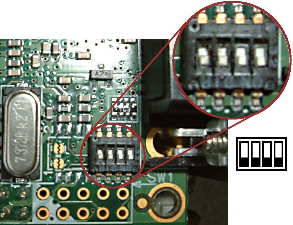 The EB675001DIP can now boot from NOR flash. This is selected by setting DIP
switches 3 and 4 (Boot 0 and Boot 1) to the on position. This
should be done with the module power turned off.
The EB675001DIP can now boot from NOR flash. This is selected by setting DIP
switches 3 and 4 (Boot 0 and Boot 1) to the on position. This
should be done with the module power turned off.
Apply power to the module
Turn on the external DC supply.
Verify correct operation
The minicom display should show ABLE booting correctly.
Simtec OKI M67500X
SDRAM: initialising
SDRAM: probing...
00000001.
00001234.00001234
SDRAM: 02000000
Copying ABLE to SDRAM
Preparing to remap for execution
ABLE: 2.09 (oki-eb67dip,oki-m67x) (vince@gerald) Thu Jun 16 18:22:03 BST 2005
Processor: Oki ML67500x (ARM720T)
System: Machine eb67dip/oki-ml67x, Linux id 0x01c6
Bootswitch configuration 20
EEPROM: 24cXX, 1024 bytes, single byte addressed, UID 00.00.06.00
(nvram0) on (24cxxp1)
selected all-wr for console write
selected all-rd for console read
DRAM: 32 Mb (33554432 bytes)
Ricoh R2051K, 15:3b:34, 12hr mode
ABLE 2.09 (C) 2001-2005 Simtec Electronics
RedBoot partition 'ABLE': (flash0) on (nor0p1)
RedBoot partition 'RedBoot': zero length, not adding
RedBoot partition 'RootFS': (flash1) on (nor0p2)
DM9000: dm0: r1, 00:11:ac:00:06:00 int phy, link down
Performing this procedure with Hyperterm under Windows
Setting the Boot DIP switches to boot from OKI ROM Loader
The
OKI ML675001 SOC has a 4k boot ROM this ROM based loader
is selected by setting DIP
switches 3 and 4 (Boot 0 and Boot 1) to the off position. This
should be done with the module turned off.
Identify which serial port the unit is connected to
Identify which serial port the EB675001DIP is connected to and ensure a note is made of the correct COM port, e.g. COM1 or COM2.
 Start
HyperTerminal and create a new connection. When asked which modem
to use, instead choose the appropriate COM port, as noted
earlier. Then select 115200 bits per second, 8 data bits, no
parity, 1 stop bit and no flow control.
Start
HyperTerminal and create a new connection. When asked which modem
to use, instead choose the appropriate COM port, as noted
earlier. Then select 115200 bits per second, 8 data bits, no
parity, 1 stop bit and no flow control.
Apply power to the module
Sending 5k of zeros to initialise OKI ROM Loader
 This is achieved with Hyperterm from the Transfer menu by selecting the "Send Text File" item. The 5k-zeros.txt file should then be selected for upload.
 Once uploaded Hyperterm should output the word "Ready"
Sending "Downloader" IPL
 The "Downloader" IPL is also transfered using the "Send Text File" menu entry. The eb67xxxx-dl.hex.txt file should be selected for upload.
 Once the transfer is complete Hyperterm should display the "Select next operation " prompt, answer by typing 1
The Downloader utility has now been transfered into SRAM by the OKI ROM boot program, it will initialise the DRAM of the EB675001DIP and start an X Modem transfer into the SRAM.
Using XModem to upload ABLE RAM load version
 Once
the "Downloader" IPL is running Hyperterm should display
the XModem download tool announcement.
Once
the "Downloader" IPL is running Hyperterm should display
the XModem download tool announcement.
 On
the Transfer menu of Hyperterm the "Send File" option
should be selected. The eb675001dip-able-ram-v209.bin RAM copy of
ABLE should be entered into the filename section and XModem
selected as the Protocol.
On
the Transfer menu of Hyperterm the "Send File" option
should be selected. The eb675001dip-able-ram-v209.bin RAM copy of
ABLE should be entered into the filename section and XModem
selected as the Protocol.
 Once the transfer is started Hyperterm displays its status until complete.
 Once the transfer is complete ABLE will start as usual.
Using the ABLE command line to write a fresh copy of ABLE to flash
Once executing the ABLE command line may be used as normal (see the ABLE Documentation for details on ABLE use.)
 Assuming a tftp server is available with the
romwrite version of ABLE this may be
used to program the NOR flash as would be performed for any normal
flash upgrade by simply booting the image.
Assuming a tftp server is available with the
romwrite version of ABLE this may be
used to program the NOR flash as would be performed for any normal
flash upgrade by simply booting the image.
Remove power from the module
Turn off the external DC supply.
Setting the Boot DIP switches back to boot from NOR flash
The EB675001DIP can boot from NOR flash this is selected by setting DIP
switches 3 and 4 (Boot 0 and Boot 1) to the on position. This
should be done with the module power turned off.
Apply power to the module
Turn on the external DC supply.
Verify correct operation
The minicom display should show ABLE booting correctly.