When a platform is initially powered or a hard reset performed, the ABLE environment will be started and each component module will be loaded in turn. The last module loaded is the ABLE shell, which will present the user with a command line interface.
ABLE has the ability to use a combination of input and output sources to interact with a user. The default is to use all the input and output devices available. For example, on the EB2410ITX both the console serial port and the video display will be used to output and the serial port for input (future versions may support USB keyboards for input).
Example 3.1. Video display after starting ABLE on EB2410ITX
selected all-wr for console write stream
selected all-rd for console read stream
DRAM: 128 Mb (134217728 bytes)
BAST: PMU version 1.02, ID 00:01:3d:00:01:6a
ABLE: 2.08 (s3c2410x) (vince@gerald) Fri Apr  8 16:35:26 BST 2005
hdc: TOSHIBA MK1003MAV: ATA PIO mode 4
hdc:Diagnosing disc drive: ok
(hdc) 1GB
(hd0) on ((hdc1):ext2)
(hd1) on (hdc2)
DM9000: dm0: r1, 00:01:3d:00:01:6a int phy, link ok, 100Mbit full duplex
NE2000: ne0: ISA/Generic, 00:01:3d:00:01:6b (EEPROM Invalid / Missing)
TMP101: I2C error (-2)
sys.autoshadow unset, automatically shadowing
>
Example 3.2. Serial display after starting ABLE on EB2410ITX
SuperIO controller fitted
Initialising
Detecting SDRAM size
SDRAM: BANK6 size 04000000
SDRAM: BANK7 size 04000000
ABLE: 2.08 (s3c2410x) (vince@gerald) Fri Apr  8 16:35:26 BST 2005
Processor: Samsung S3C2410A (arm920)
System: Machine bast/s3c2410x, Linux id 0x014b
.S3C2410X RTC: 01:46:54, 00/01/2003
NAND: configured boot slot is 0 (card slot)
NAND: found Samsung K9F1208u0a [131072,32,512]
(flash0) on (nand0p1)
(flash1) on ((nand0p2):jffs2)
EEPROM: 24cXX, 1024 bytes, single byte addressed
(nvram0) on (24cxx)
sys.speed is unset, Setting CPU Speed to 266MHz
no configuration, defaulting to VGA
X/Y values invalid, configuring automatically
Chrontel CH7006 detected
screen mode is 640x480, ?Hz, ?Hz HSync
video: video size 300K
configuring ch7006: vga
selected all-wr for console write stream
selected all-rd for console read stream
DRAM: 128 Mb (134217728 bytes)
BAST: PMU version 1.02, ID 00:01:3d:00:01:6a
ABLE: 2.08 (s3c2410x) (vince@gerald) Fri Apr  8 16:35:26 BST 2005
hdc: TOSHIBA MK1003MAV: ATA PIO mode 4
hdc:Diagnosing disc drive: ok
(hdc) 1GB
(hd0) on ((hdc1):ext2)
(hd1) on (hdc2)
DM9000: dm0: r1, 00:01:3d:00:01:6a int phy, link ok, 100Mbit full duplex
NE2000: ne0: ISA/Generic, 00:01:3d:00:01:6b (EEPROM Invalid / Missing)
TMP101: I2C error (-2)
sys.autoshadow unset, automatically shadowing
>
The input devices are controlled by using the cons-read parameter and similarly the cons-write parameter controls which output devices are used.
Typically the console serial port is used to interact with the ABLE CLI.
Unless the boot parameters are altered from their default settings the autoboot process will commence. To manually start an Operating System the command line must be used.
To access the serial console from windows the hyperterm program can be used. Identify which serial port the platform is connected to and ensure a note is made of the correct COM port, e.g. COM1 or COM2.
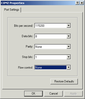
Start HyperTerminal and create a new connection. When prompted for which modem to use, instead choose the appropriate COM port, as noted earlier. Then the appropriate settings for your platform (please refer to platform specific documentation) typically these settings are 115200 bits per second, 8 data bits, no parity, 1 stop bit and no flow control as shown in Figure 3.1, “Hyperterm settings window”.
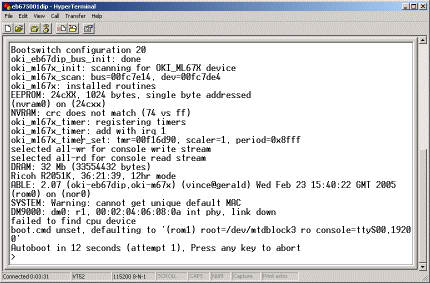
Once the connection is established the output from ABLE should be seen in the hyperterm window as in Figure 3.2, “Hyperterm displaying ABLE output”
To access the serial console from LINUX® the minicom program can be used. Identify which serial port the EB2410ITX is connected to and ensure a note is made of the correct device node, e.g. something like /dev/ttyS0 or /dev/ttyUSB0.
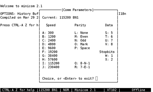
Start minicom and ensure the correct settings are selected (Default is Ctrl-A p). These settings are 115200 baud, 8 data bits, no parity and 1 stop bit as shown in Figure 3.3, “Minicom settings window”. Obviously Minicom should be using the correct serial port as noted earlier.